[ home | FAQ | project | download | prototype | community | links ]
The objective is to use readily available "off-the-shelf" low-cost consumer components where possible, and to design electronic subsystems where such components are either not readily available or are too expensive. In terms of affordability, the overall goal is to design a robot that can be made for around the price of a PC (US$1,500 to $2,000 is the target, but the actual cost of building a robot can vary greatly depending on how many of the electromechanical components are made in your own workshop versus purchased pre-fabricated).
 Overview
The block diagram below identifies the major hardware components that comprise the robot and its accompanying docking station. The cyan coloured blocks represent custom electronic circuits - all microcontroller based with firmware - that have been developed within the scope of this project.

 Operating System
The free and open GNU/Linux operating system has been chosen as the foundation for the software in this project. Kernel and device-driver source code is readily available and well supported by the developer community.
 Mainboard
The requirements of the mainboard are:
 Software Framework
The hardware subsystems of this project are abstracted using the Player driver framework, originally developed at the University of Southern California Robotics Lab.
The Pyro project, developed at Bryn Mawr College in Pennsylvania, provides a higher-level framework that builds upon the Player driver layer to allow experimentation with behaviours and tasks.
 Sensors
Vision is central to the success of the project. Several sources of pre-existing code are being researched:
The binocular colour vision system is based on a pair of consumer WebCams using the FireWire (IEEE 1394) interface. The Pyro 1394 WebCam from ADS was chosen for development. This device has a 1/4" colour CCD image sensor with a resolution of 659x494 (although the maximum WebCam interface format supported is 640x480). The WebCam has a glass lens with a focal length of 4mm, an F number of 2.0, and a viewing angle of 52°. Any IIDC-compliant (a.k.a. DCAM) digital camera should work (note that this does not include DV camcorders; these are not IIDC-compliant). Here is a list of compatible digital cameras.
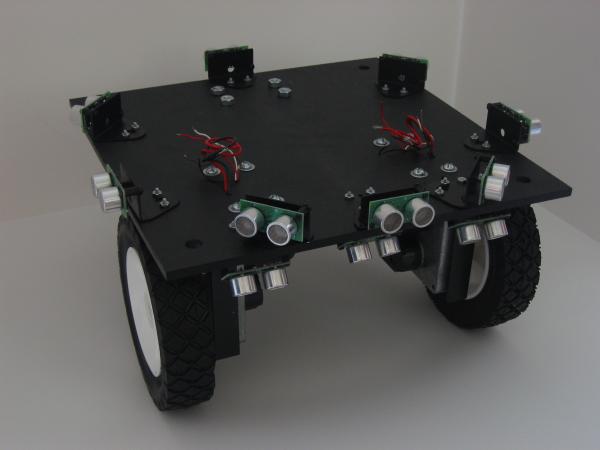
A sonar sensor array augments the vision system for detecting objects in the robot's environment. The Devantech SRF04 has been chosen due to its high performance and low cost compared with sensors based on the ubiquitous Polaroid sonar transducer. The amazingly small minimum range of 3cm measurable by the SRF04 also makes it suitable to use as a downward facing precipice detector to sense floor discontinuities (although in practice this has been found to be effective only for hard floors; carpets tend to absorb the sonar sound).


The sonar array module, which is based on a PIC16F876 microcontroller, supports up to a maximum of 16 SRF04 sonar sensors. The module fires the sensors sequentially at 25ms intervals, allowing a full scan of 16 sensors to be completed in 0.4s. It interfaces with the host mainboard via I2C.
A command-line utility program oap-sonar, that runs on the robot's mainboard system, performs the following functions:
One passive infrared sensor mounted on the pan-and-tilt head allows the robot to detect sources of heat such as humans. The Eltec 442-3, which is tuned to the human body's infrared emissivity, is well suited for this application.

 Human Robot Interface
There are currently three parts planned to the human-machine interface. These are (a) speech output, (b) a minimalist robot-mounted graphical user interface with a small LCD screen and a keypad, and (c) remote control. Speech input is perhaps conspicuous by its absence from this list; it has been decided that at least for the initial scope of this project, voice recognition will not be attempted.
Speech synthesis is implemented using the Festival Speech Synthesis System from The Centre for Speech Technology Research at the University of Edinburgh.
Although VGA compatible mini-LCD kits are readily available, these are prohibitively expensive (typically $300 or more), so a small 4-line, serial interface, character mode LCD module with backlight was chosen as the GUI output device. The 634 Intelligent Serial Display from Crystalfontz has been chosen for development. This device is compatible with the LCDproc display driver.
The primary human input device is a small custom-designed keypad for direct connection to the PC's (PS/2 style) keyboard socket. This is driven by a PIC16F84 microcontroller, which also converts remote control commands that it receives into simulated keystrokes.
Both infrared and a radio remote interfaces have been developed. The infrared interface utilizes the Sony IR protocol, so it is compatible with practically all universal remote control units. The radio remote control interface allows the robot to be summoned from another room, or ordered to a location while it is out of range of IR. A custom transmitter unit has been developed based on a PIC16F84 microcontroller.
 Pan and Tilt Head Control and Heat Source Sensor Interface
A microcontroller-based module with an I2C interface to the host, drives the servos of the Pan and Tilt head, upon which the vision sensors, passive infrared sensor, and one of the sonar sensors are mounted.
A secondary function of this module is to interface with the passive infrared sensor, passing data back to the host about the direction the head was "looking", and the time when a heat source was detected.
A command-line utility program oap-head, that runs on the robot's mainboard system, performs the following functions:
 Locomotion
A microcontroller-based motor control module is responsible for generating high frequency PWM signals for the two main DC drive motors, and for counting the pulses from two quadrature encoders. The module passes motor drive commands from the host, and pulse counts back to the host via the I2C interface, using the SMBus protocol.
A command-line utility program oap-motor, that runs on the robot's mainboard system, performs the following functions:
 On-Board Power Management and Docking/Charging Station
A microcontroller-based power management module on board the robot is responsible for monitoring battery voltage, sensing when the robot is docked with the fixed charging station and activating the charging cycle. The robot-mounted Power Management Module beams commands to the fixed floor-based Docking Station via PWM infrared packets (using the same modified Sony protocol used by the Input Module). The Power Management Module communicates with the host mainboard via the I2C interface, using the SMBus protocol, to report battery voltage and charging status.
A command-line utility program oap-power, that runs on the robot's mainboard system, performs the following functions:
 I2C Parallel Port Interface (untested)
This hardware module, which plugs into the mainboard's parallel port, was developed to allow mainboards without an I2C header to interface with OAP's other I2C modules. It was designed to work with Simon G. Vogl's I2C Linux kernel driver, i2c-philips-par.
This module is not required for mainboards that have their own integrated I2C interface (as long as it's supported by the Linux kernel).
|
|
Copyright © 2001-2009 Dafydd Walters. All rights reserved. This page was last modified on November 27, 2009 |
|